Build Your Own 3D-Printed Az-El Antenna Mount: A Step-by-Step Guide
Introduction
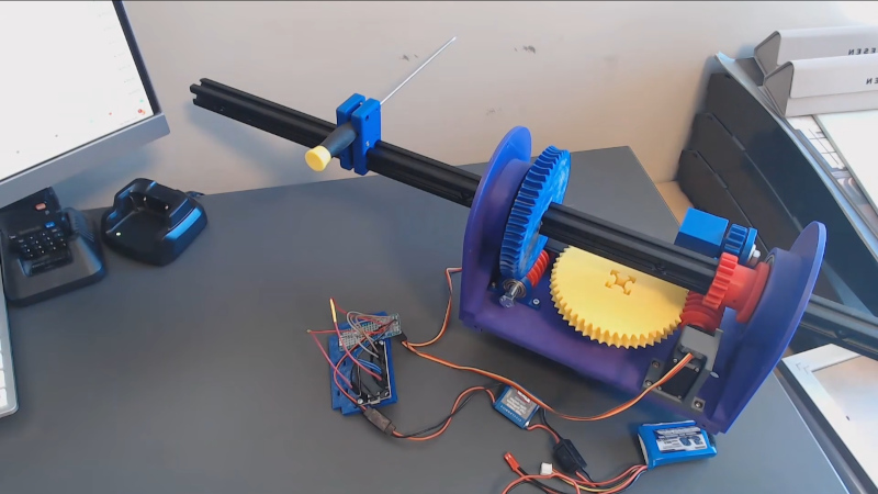
Tracking non-geostationary satellites requires a mount that can move in two axes—azimuth (horizontal rotation) and elevation (vertical angle). This is where an azimuth-elevation (Az-El) mount becomes essential. Inspired by the work-in-progress from Ham Radio Passion, this guide walks you through constructing a compact, 3D-printed Az-El mount that uses a 360-degree servo with a worm-drive mechanism. The design is straightforward, prints easily, and is ideal for higher-frequency antennas that don't need massive arrays. Follow these steps to build your own tracking mount.
What You Need
- 3D Printer (PLA or PETG filament recommended)
- Aluminum extrusion (for the antenna arm, e.g., 2020 profile)
- 360-degree continuous rotation servo (with worm drive capability)
- Worm gear and spur gears (STL files from the project)
- Mounting hardware (screws, bolts, nuts, washers)
- Microcontroller (e.g., Arduino or ESP32) with servo library
- Power supply (adequate for servo)
- Antenna (small, directional for higher frequencies)
- Basic tools: screwdrivers, pliers, Allen keys
Step-by-Step Instructions
Step 1: Print the Az-El Mount Components
Begin by downloading the 3D models from the project repository (typically provided by Ham Radio Passion). Print the following parts:
- Turntable base – the rotating platform for azimuth.
- Elevation bracket – holds the antenna arm and pivots.
- Gear housings – enclosures for the worm and spur gears.
- Arm adapter – connects the aluminum extrusion.
Use a layer height of 0.2 mm, 20% infill, and supports where necessary (especially overhangs). Post-process by removing brims and smoothing holes with a drill bit if needed.
Step 2: Prepare the Aluminum Extrusion
Cut a length of aluminum extrusion to serve as the antenna arm. A common size is 300–500 mm long—enough to mount a small Yagi or patch antenna. Drill mounting holes at both ends: one for the elevation pivot bolt, the other for the antenna bracket. Deburr the edges to avoid injury or damage to the 3D-printed parts.
Step 3: Assemble the Azimuth Turntable
Attach the printed turntable base to a solid foundation (e.g., a tripod plate or heavy wooden board). Insert a bearing (if included in the design) to allow smooth rotation. Mount the 360-degree servo on the turntable, aligning its output shaft with the center of rotation. Secure the servo using screws and the printed servo mount. Ensure the servo horn can freely engage with the worm gear.
Step 4: Install the Worm Drive and Gears
The worm drive provides high torque and self-locking capability—crucial for holding elevation steady. Install the worm gear on the servo shaft, then place the spur gear (linked to the elevation axis) so they mesh properly. Use printed gear housings to keep alignment tight. Lubricate with a tiny amount of silicone grease for smoother operation.
Step 5: Build the Elevation Mechanism
Connect the elevation bracket to the turntable using a hinge pin or bolt. This bracket will pivot up and down. Attach the aluminum extrusion to the bracket using the pre-drilled hole. The extrusion should be free to move but without wobble. The elevation axis should be perpendicular to the azimuth axis.

Step 6: Mount the Antenna
Secure your directional antenna to the free end of the aluminum extrusion. For higher frequencies (UHF, SHF), even a small dish or helix antenna will work. Use hose clamps or U-bolts to hold it firmly. Ensure the antenna’s feed point is accessible for coaxial cable connection.
Step 7: Wire the Servo and Microcontroller
Connect the servo signal wire to a PWM-capable pin on your microcontroller (e.g., Arduino pin 9). Power the servo from a separate 5V or 6V supply (do not draw from the Arduino’s 5V pin if the servo is high-draw). Grounds must be common. Write a simple sketch to rotate the servo to specific angles—for testing, sweep from 0 to 180 degrees repeatedly.
Step 8: Calibrate and Test
Power up and check the full range of motion. The azimuth should rotate 360° without binding, and elevation should move from horizontal (0°) to vertical (90°) or more. If the servo stalls, adjust the gear mesh or reduce friction. Use a protractor to verify angles. Once calibrated, you can program tracking routines for specific satellites.
Tips for Success
- Start small – Test with a lightweight antenna before adding a larger array.
- Watch the project – Ham Radio Passion updates often; check for improved STL files or firmware.
- Consider backlash – 3D-printed gears may have play; use anti-backlash techniques or tighter tolerances.
- Weatherproof if using outdoors – Apply conformal coating to electronics and seal print seams with epoxy.
- Use a stepper motor alternative – If you need higher precision, replace the servo with a stepper motor + driver (NEMA17) and a toothed belt.
- Check alignment – Ensure the azimuth axis is perfectly vertical; even a slight tilt throws off tracking.
- Document your build – Share your modifications on forums; the community benefits from collective experience.
This Az-El mount is a work in progress, but it already shows promise for satellite communication enthusiasts. By following these steps, you can get a functional, low-cost tracking mount that handles small directional antennas with ease. Happy building!
Related Articles
- The Cracks in AI's Foundation: Insights from Five Industry Architects
- How Australia Can Ditch Fossil Fuels and Reach Real Zero: A Blueprint from Andrew Forrest's Fortescue Model
- Razr Fold vs Galaxy Z Fold 7: My Verdict on the Better Foldable
- The Deep-Sea Secret of Squid Survival: New Genome Research Unveils Ancient Escape Routes
- Clean Room Upgrades Pave the Way for Roman Space Telescope Processing at Kennedy
- Explore NASA's Summer STEM Programs: From Coding to Career Insights
- 7 Key Insights from NASA Wallops' Upcoming Public Information Session
- AirSnitch Attacks: How Enterprises Can Defend Against Wi-Fi Encryption Breaches