How to Build an E-Bike Motor from Scratch: A Step-by-Step Guide
Introduction
Building your own electric motor from first principles is a challenging but rewarding project. Inspired by the work of [Birdbrain] on Hackaday, this guide walks you through the process of designing and constructing a custom e-bike motor. You'll learn to select core materials, wind coils, 3D-print a housing, and choose the right motor driver—all without buying a pre-made motor. While the original project didn't mount the motor on a bike, the principles apply to any electric vehicle. Ready to dive into electromagnetism and fabrication? Let's get started.

What You Need
- Transformer laminations (old microwave oven or power transformer cores)
- Magnet wire (various gauges, e.g., 0.5 mm to 1 mm)
- Strong neodymium magnets (e.g., N52 grade)
- 3D printer and filament (PLA or PETG; ABS for higher heat tolerance)
- Bandsaw or sheet metal shear for cutting laminations
- Motor controller (trapezoidal or sine-wave type)
- Multimeter, soldering iron, and basic electronics tools
- Simulation software (e.g., FEMM or online motor calculators)
- Safety gear: goggles, gloves, fire extinguisher
Step-by-Step Instructions
Step 1: Design Your Motor with Simulation
Start by defining your motor's target: power, RPM, and voltage (e.g., 500 W, 3000 RPM, 48 V). Use free simulation tools like FEMM (Finite Element Method Magnetics) to model the electromagnetic design. Choose between a brushless DC (BLDC) or permanent magnet synchronous motor (PMSM) topology. For an e-bike, BLDC with a trapezoidal waveform is common. Input parameters: number of poles (e.g., 8), number of slots (e.g., 12), winding configuration (concentrated or distributed), and wire size. The simulation predicts torque, efficiency, and heat. Birdbrain used a simulation to optimize her core and winding pattern before cutting metal.
Step 2: Cut and Stack Transformer Laminations
Salvage laminations from an old transformer—they're thin sheets of silicon steel that reduce eddy currents. Using a bandsaw, carefully cut them to the shape of your stator core (usually an annular ring with teeth for windings). Stack the laminations to your desired thickness (e.g., 20 mm). Birdbrain used a bandsaw to achieve precise shapes. After cutting, deburr edges with a file. Ensure the stack is tightly clamped during cutting to avoid shifting. You can also use laser cutting for cleaner edges if available.
Step 3: 3D Print a Housing (and Reinforce It)
Design a housing in CAD that holds the stator core and allows the rotor (with magnets) to spin. Print using a 3D printer—Birdbrain initially used PLA, but found it too weak to withstand the magnetic forces (magnets can pull with several kilograms of force). Redesign the housing to be thicker, or switch to PETG or nylon. Add mounting points for bearings and a shaft. If possible, embed metal inserts for strength. Birdbrain's second print succeeded by increasing wall thickness and using a higher infill (100%).
Step 4: Wind the Coils and Assemble the Rotor
Wind magnet wire around each stator tooth according to your simulation's turn count (e.g., 15 turns per tooth for 48 V). Use a winding jig or do it manually—keep tension consistent to avoid loose coils. Connect coils in the correct phase pattern (A, B, C) for BLDC. For the rotor, glue neodymium magnets onto a 3D-printed or metal rotor ring with alternating polarity (N-S-N-S). Use a jig to align them precisely. Birdbrain recommends epoxy and careful handling—magnets can snap together violently. Test the rotor-stator air gap: it should be as small as possible (e.g., 0.5 mm) without touching.
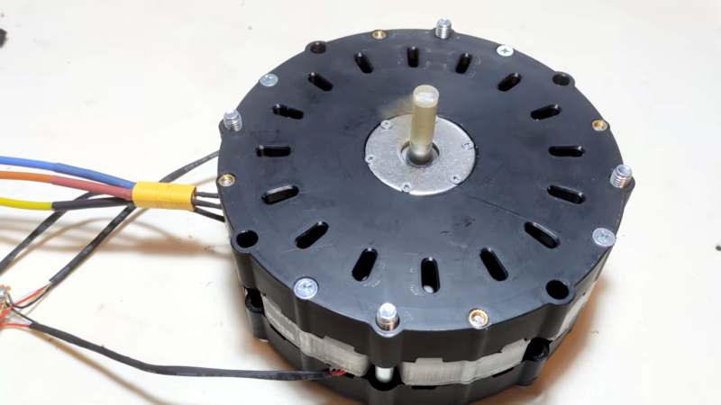
Step 5: Choose and Wire a Motor Driver
Not all motor controllers are equal. Birdbrain tested cheap drivers (e.g., generic sensored BLDC controllers) and found they produced poor waveforms, leading to cogging and inefficiency. For a custom motor, use a sine-wave driver or a field-oriented control (FOC) driver that can be tuned. Alternatively, build your own using an open-source ESC (e.g., VESC). Wire the three phase wires from the motor to the driver, and connect Hall effect sensors if you have them (for sensor-based control). With a good driver, the motor will run smoothly. Birdbrain's motor spun up nicely after switching to a better driver.
Tips for Success
- Safety first: Magnets can shatter and cause injury; wear goggles when handling. Lamination cutting produces sharp metal edges.
- Test incrementally: Before full assembly, spin the rotor by hand to check for binding. Measure resistance and inductance of each phase.
- Heat management: At high loads, the motor will get hot. Consider adding ventilation slots in the housing or a small fan.
- Iterate on design: Birdbrain went through multiple 3D prints. Don't expect perfection on the first try—simulation helps but real-world testing reveals issues.
- Learn from others: Join maker forums (e.g., Endless Sphere) to refine your motor design and driver settings.
- Alternative route: If building from scratch feels too daunting, repurposing a car alternator is a simpler path (as covered in a previous Hackaday article).
Building a motor from first principles is a fantastic way to understand electromagnetic basics and push your fabrication skills. Good luck, and may your e-bike be powered by your own creation!
Related Articles
- From SMS Phishing to SIM Swapping: How 'Scattered Spider' Executed a Multi-Million Dollar Crypto Heist – and How to Stop It
- Securing Canvas Login Portals Against Extortion Attacks: A Comprehensive Guide for IT Administrators
- 10 Proactive Defenses Against Hypersonic Supply Chain Attacks: A Blueprint for 2026
- Cloudflare Slashes 1,100 Jobs in Major AI Overhaul, Shares Dive Despite Strong Q1
- Cyber Automation Race: Attackers Use Machine Speed to Overwhelm Human Defenders
- Your Weekly Security Checklist: Protect Against SMS Blasters, OpenEMR Flaws, and Roblox Hacks
- How to Secure Your WordPress Site Against Avada Builder Plugin Vulnerabilities
- 8 Critical Facts About the Windows MiniPlasma Zero-Day Exploit Granting SYSTEM Access